Designing, developing, building and testing a complex audiophile project is a workflow that requires a number of tools. As I learn and get better, and as communities develop ever better open-source and freeware toolsets, the job is made easier.
What did Franklin say? “If you want to chop down a tree, take time to sharpen your axe”
Workflow
Engineering is not necessarily a linear process. Indeed, modern methods centre on the principle of fail fast & learn. These “agile” principles have stood the pressure test in my professional life and are evermore deployed as the complexity of the project increases.
SpaceX is a fine example. Building a rocketship that goes to the moon perfectly first time is exponentially difficult. However, building, testing, blowing up, learning, then going again has resulted in the industrialisation of space flight SpaceX is perfecting today
Let’s adopt some principles:
- Accept that iterations are a good thing
- Plan iterations as cycles of learning
- Carefully consider what needs to be learnt ahead of the development cycle (aka sprint)
To get to a high-performance product: three main elements have to be conceived, developed, built, integrated, then tested. The whole process will lead to learning that is the feedback for the next version.
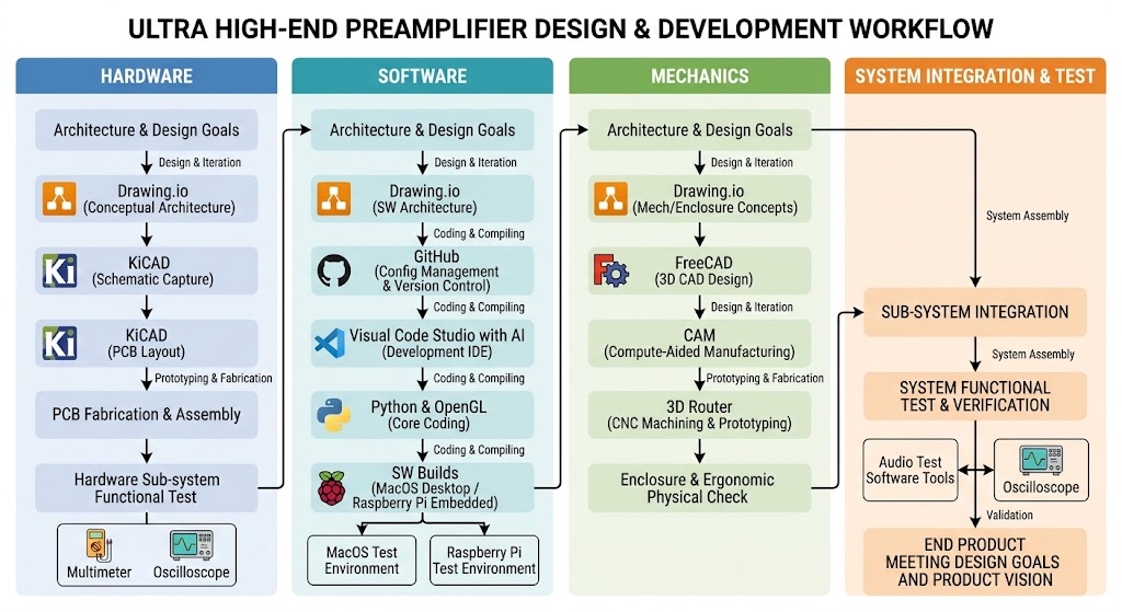
I want to summarise the steps each of the elements goes through and the tools/methods used in the design process, culminating in the sub-system and overall system integration and functional test to verify the end product meets the design goals and product vision.
The high-level steps of the workflow that are iterated on overall and at each stage are:
- Product vision, design goals, system architecture and integration
- Hardware specification: functional and non-functional (eg safety, EMC)
- Software features and architecture
- Mechanical specification, functional and ergonomic (eg user interface)
Product Vision and Integration
The workflow starts and ends with the overall product concept and ends with all the elements integrated together to make a whole product system that performs to the product overall specification.
The steps are:
- Product concept:
- Aims, aspirations, features – without realworld constraints
- Acceptable tradeoffs eg Ease to build, cost, part selection
- User interface, inputs and outputs
- Following the Analogue Hardware, Mechanical and Software developments comes system integration:
- Verification that the PCBs, power supplies, controllers, sockets, heat dissipation, electromagnet isolation etc all interact as designed
- System testing: do all the parts come together as a whole to meet the overall product specification: functional and non-functional
- Real-world tests – is it usable, what would make it better, how could the vision be improved? The optimisation is a cruical step to create a product of value.
Analogue Hardware
The Hardware development comprises the following steps:
- Performance specification: [text]
- Measurable parameters eg Signal to Noise, THD+N
- Input, output details
- Functions
- Overall HW architecture: [Open.io, text]
- Block functionality
- Design decisions on how elements interrelate
- Circuit design: [KiCAD]
- Circuit diagrams
- PCB Design: Gerber files [KiCAD]
- Component selection: Bill of Materials (BOM) [KiCAD]
- Component sourcing:
- Procurement: EBay, Farnell, Mouser, Alibaba
- PCB Manufacture: PCBWay, JLC
- Circuit Construction
- Circuit test
Software Development
Software for an embedded product is more easily developed in a powerful environment (eg. Mac desktop) then cross-compiled onto the target environment for performance optimisation. Functions eg screen layout and user controls are where the features come to life. But the non-functional aspects eg speed of response, smoothness, robustness in failure scenarios is where SW goes from being a quick and dirty software build to a professional-grade repo.
Experience shows that embedded products need as much or more effort spent on the non-functional aspects for a worthwhile outcome.
The development steps comprise:
- Features and performance specifications [text]
- Software architecture: [drawing.io]
- Diagrams
- API specifications
- Design pattern choice eg Model-View-Controller (MVC):
- Model represents the Data and functional logic.
- Controller handles the Control flow and input logic.
- View handles the user interface and presentation layer.
- HW abstraction layer: interfaces to the underlying hardware
- Software class definition: [python]
- Shader definition: [OpenGL]
- Code development: [Visual Code Studio]
- Use of AIs for code generation, idea generation and testing are all key productivity boosters
- Software test:
- python test harness
- timing instumentation
- porting to target environment
- overall functional and non-functional testing
Mechanical Development
As human we interact with physical things. We look at them, touch, hear and interact with them. The ergonomics of the product is considered in two layer:
- Physical knobs, buttons, screen, connectors, mechanical enclosure
- Functions and features: all implemented in Hardware and Software, interacting with the real-world controls.
This makes the design of the Mechanics, Hardware and Software all interdependent and co-dependent. The design process is about deciding on acceptable tradeoffs in one realm that managed in other. eg Touchscreen controls rather than buttons.
The mechanical design process is:
- Mechnical specification: size, weight, connectors, EMC, safety etc: [text]
- Mechanical architecture: [drawing.io]
- Concept renders
- Physical user interface
- Mechanical design: [FreeCAD]
- Enclosure layout of main elements eg Transformers, PCBs, connectors
- Front panel design
- Back panel design
- Cutting & drilling list for 3D router
- Part sourcing: BOM
- Mechnical build and assembly
Synchronised Development & System Convergence
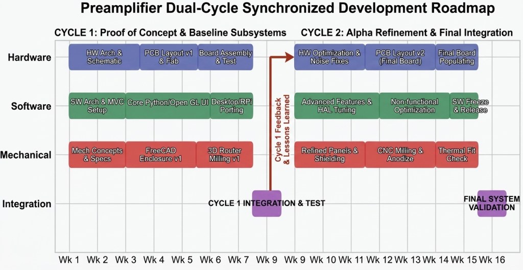
While it is convenient to map out Hardware, Software, and Mechanics as isolated tracks on a diagram, real-world engineering demands that they march in lockstep. You cannot finalise a PCB footprint in KiCAD without knowing the enclosure mounting constraints in FreeCAD; likewise, you cannot optimise your OpenGL screen layout or response times in VS Code without knowing the physical display dimensions and the Raspberry Pi’s target compute performance. This interdependency means all three streams must be executed in concert. By structuring the project into distinct, synchronised development cycles (Sprints), we ensure that early prototypes across HW, SW, and Mechanics converge at defined integration milestones. Each cycle culminates in a full subsystem and system test—exposing thermal issues, ground loops, or UI latency early—so that the lessons learned directly feed the next iteration. It is this orchestrated cadence that turns a collection of high-end parts into a cohesive, audiophile-grade product.
This is how the project timeline could look. Frankly, 16 weeks is ambitious!


Leave a comment